
Section 3: Electronics
CL-FBS Hardware and Software Guide
When it comes to the electronics of a Protogen helmet there is a lot that can be done! All types of different displays, sensors and features to choose from. However, for this guide you have chosen to use our specifically made Protogen tech to give you premium features with as little learning and hassle as possible. Let's get into it!
This will be all the items needed to complete your Protogen tech set up
Materials/Tools
Soldering Iron
Solder
Wire Cutters/Strippers
20AWG Flexible Stranded Wire
Small needle nose pliers
Hot glue gun + glue
FurBitten MAX7219 Style Frame- Ultimate
FurBitten Ultimate Style Cheek Caps
Helping Hands Soldering Aid (optional)
Soldering Flux (optional)
Cable Management items (optional)
Hardware
CL-FBS PCB Panel
1.25" I2c OLED Screen
FurBitten Studios MAX7219 14 String
Led Strip Lights (5v)
13mm Momentary Push Button
C-USB cable
4P JST GH Cable (2x)
6P JST GH Cable
JST SM Connector Plug (optional)
Main Face assembly
Step 1:
Prep your boards by applying solder to the end connection points. This will be easier than trying to prep the pads with the displays in the frame. This is not required however, and you can do this after Step 2 if you wish.
Step 2:
!!IMPRORTANT!!
Do not glue in your LEFT eye (the eye with the pins on the back) just yet. We must first assemble it before we glue it into the frame
Grab your displays, MAX7219 Frame, and hot glue gun. We will be gluing the displays to their designated spots. Be sure your displays are placed correctly! If Ragnar is upside down, so is your display.
I recommend glue in your displays in this order
Maw boards → Eye boards → Nose Boards
NOTE: You do not have to glue in the displays and then wire them. FurBitten Studios does this to keep wires as short and managed as possible. You can wire them together first and then glue the setup into the frame if you wish.
Step 3:
Wire Prep! We are going to measure and cut all out needed wires for the displays.
List:
-
1 size- Eye to mouth X10
-
1 size- Mouth to nose X10
-
1 size- nose to nose X5
You will measure your wire from the OUT of one board to the IN of the next board; make sure you are going to the correct connections, VCC to VCC, CL to CL etc. You only need to measure once for each needed size and then duplicate your wire size using your first one as a measuring guide.


You may run your wires however you wish. As long as the connections are correct.
FurBitten Studios simply tries to keep things as tidy as possible.
Step 4:
With your matrices in place and your wires cut, it's time to grab your wire strippers and heat up your soldering iron! Start with stripping the ends of your wires and applying some solder to the stripped ends

Step 5:
Remember that left eye from Step 2? It's time to grab that, 5 of your long wires, your main control board (the big one), and board cover.
Begin with soldering your wires to the out of your left eye.

Step 6:
Place the control board on the back of the left eye as you see in the image below. Solder the control board to the eye and snip the pins off. If you do not cut the pins then your case/cover will not sit properly on the board.
NOTE: If you are not using different color wire please ensure your wires stay in order when you place the control board on top or mark the ends with a marker to identify which wire is which. This is to ensure you wire the eye to the maw below it correctly.

Step 7(optional):
Before you place your cover on if you would like to seal your 5 out connection points in hot glue to help seal out moisture, please do so now. Otherwise, you may put on the cover to protect the board as we continue to work.
NOTE: If needed you may apply alitle supper glue to an edge of the case and board to help keep it on if for whatever reason your cover is a touch loose.


Step 8:
With your Control eye now assembled you may now glue it into place in your frame and begin wiring together all the displays.

Step 9(optional):
If you would like to seal all your wire points in hot glue to help seal from moisture, please do so now
Nose Sensor Assembly
Set aside your main face set up and grab the following items: CL-FBS mic, bus, and boop. Your 4pin(both) and 6pin cables. OLED Screen. Nose Sensor frame piece.
Step 1(optional):
Grab 1 of the 4 pin cables and your 6 pin cable. If you would like to bind them together to make a single more managed cable, please do so now. You may use whatever management your prefer, FurBitten Studios personally likes to use automotive wire harness tape
NOTE: If you are going to bind them please leave room at both ends so you have more freedom to flex the connectors to their ports. This is important for later.

Step 2:
Grab your CL-FBS bus and your OLED. Attach the bus to the back of your OLED
NOTE: Due to the fact there are 4 different variants of this screen the bus is designed with a snap point if needed should power and ground be swapped. Additionally, you may need to put the bus on upside-down dispending on the variant provided in your kit. As long as the pins match it will work!


Step 3:
Its time to plug in your sensors to each other and prepare to glue in everything to the nose sensor piece. Looking at the OLED on the back, with the bus on your right side. Use your last 4pin cable to plug in your boop sensor to the TOP of the OLED Bus. The bottom bus port will be used for your bundle wire that connects your boop/OLED to the main board. Your 6pin being used for the mic. You should now have things to this stage as seen below.
NOTE: It does not matter what end you plug into each component. The only thing that matters is that things are plugged into the correct spot

Step 4:
Glue in time! Everything has a home in the nose sensor housing so messing it up is not something to worry about. Things only fit one way! You do not need a lot of glue, just enough to keep things in place. The order you glue things in though is kind of important, so a component has room to drop into place.
ORDER:
1. OLED
2. Mic (it will be a snug fit, don't be afraid to push a little)
3. Boop

Step 5(optional):
Your nose sensor assembly is done! If you would like to use some cable management item to tuck away the extra boop wire, do so now. Otherwise just kinda fold it up and it will stay out of the way unseen.

Step 6:
You can grab your main face assembly and slide on your nose sensor assembly. Be patient as this will be a pretty snug fit. Glue is not needed per say but you may use some hot glue along the edges if you would like some added security.
IMPORTANT
Make sure the bundle of wires is going out the left side along the top of your left maw board.
The wires will be too short if you try to run the wire from underneath the sensor housing


Step 7:
With all your displays and sensors installed, all wired up, the last thing to do is plug in your sensors to your control board. Ports are as follows:

On No! A Crossroad!
With your main set up done you may feel eager to jump to software. You may do that if you would like.
At this point FurBitten Studios goes to software and returns to cheek panels after simply to have them not flapping around.
Your suit may not have or need cheek lights, or you have chosen to use JST connectors and your cheek panels can be disconnected as wanted.
Cheek Caps
The cheek caps are very self-explanatory I would say. You will have a left and a right cap. The left one having an extra hole so your button wire may pass through and connect to the control board.
Step 1:
Grab some wire and connect two pieces of LED strip in the grooves on your cap. You can then use a touch of super glue to attach your diffusion covers.

Step 2:
Connect ground and power to the main face set up. How or where you do it does not particularly matter. You can do a number of options; to list afew:
1. Hard wire the Left cap to the wires between left eye and maw (your closest set of wires) - The right cap connecting directly off the out of the right eye
2. Same locations as option one but use JST connectors
3. Connect the left cap to the right by running wire along the back of the helmet - Right cap connecting to Right eye still
Theres other ways but these 3 are the most direct/simple. As long as you are not tying into any sensor cables you can tie in the power and ground from virtually any of the other wires between the displays.
Hardware Assembly Complete

Software
You've done an amazing job so far assembling your Protogen tech and it's time to get some software on there to bring it to life! You will need a computer for this section as you will need to connect your set up to your pc for upload.
At this time the software and kit are only supported for the 14 string set up!
Coming soon, compatibility/kits for 11,12, and 16 string ultimate hardware kits
Please go to Caw Labs website: CawLabs
On this website you can find the Firmware Uploader as well as the Protogen Face maker

Protogen Face Maker
You will have two options available to you for making your Protogen faces.
1. FurBitten Studios PSD file you download and draw on in a software of your own
2. Make your faces online via Caw Labs build in software
If you have chosen to use the PSD file, then you may skip this section!

Note: You may change the colors on the website to emulate what your set up will look like. Grey is in place of white. Whatever LED color you bought is the color your set up will show regardless of what color you choose to color your template with.
Step 1:
For the sake of this guide, please select option 1 "Create or edit a template" and the window will appear as shown above. FurBitten Studios default expression template will appear and if you wish you may use these! Simply click the save template PNG button and it will download it for you to be used at upload. But if you wish to great your own faces then please navigate to the "Template Style" and select choose blank
Step 2:
Hover over "Face 1" and left click to zoom in on that face. You can now begin to draw your expression for Face 1. Hold left mouse to draw, right to erase. It's so easy! You can name your face as well if you wish. While the names do show on your hud screen, your hud also shows you the full expression being shown as well.
There are buttons on the right so you may easily go to your next expression without having to go back and forth between a single face and whole template.

Step 3:
Go through all 11 faces and complete your expressions. Once complete, save the template via the button on the webpage.
WARNING
Leaving the webpage or switching back to the default expression will clear your blank template!
Firmware
Your nearly there! Youve built your set up, you've made some amazing expressions, and now it's time to light it up! Don't quit on me now!
Please head over to the Firmware Uploader page on Caw Labs website
Step 1:
Grab your setup and your C-USB cable. You will plug your control board into your PC now. There is two C-USB ports on the board, you may use either, it does not matter.
Note: If you see that your board is connecting and disconnecting periodically even though it is plugged in here is how to fix that! Unplug from the board, Hold the BOOT button on the board, while still holding the button plug back in your cable. Once plugged in let go of the button and you should have a stable connection then. This only typically happens the first time with a blank board and future hook ups should be no issue.

The control board will be the JTAG/serial debug unit if you have multiple ports in use.
When your device is connected your webpage should look similar to the screenshot below and you may click continue

Step 2:
As bugs are found, new features are made, etc. new firmware will be made and available so you may have the latest versions at all times without having to send back your tech to FurBitten Studios. If other firmware's are available at the time of your reading this select the firmware you wish to use and click continue.

Step 3:
Here at step 3 there is some things you can play with at your own pace. But for now, we will get right to the core point of getting your expressions loaded. Drop your PNG file in the " Smart file upload" section. Once loaded you will see your faces appear below the rave OLED GIF section. Then click Continue!


Step 4:
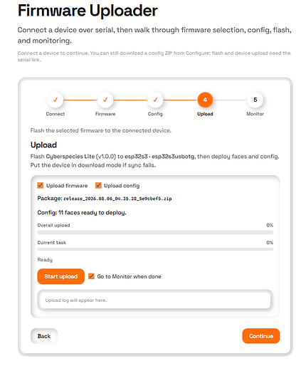
At long last we can finally actually start to upload! Ensure your screenshot looks like the one below and click "Upload". A set of progress bars will appear to show you the status of the upload. Do note that the upload does take a moment to complete. Your set up may also flash and reboot multiple times in the process, this is normal.

Step 5:
You should now be looking at some Protogen tech come to life! While on the monitor section you can change the mode to Rave mode for example to see it without using the helmet controls. A pop up will appear, click ok.
Note: Before unplugging your set up make sure you are in Main mode. Will just be eaiser for the next steps. Yes, I'm sorry. Theres just abit more left to do.

Step 6:
You may have noticed on your hud things are a touch wonky. So lets do a calibration! You may go into calibration mode if you are still at the monitor section on Caw Labs. If you are no longer at a pc you may calibrate from the set up directly by holding down the button for 30 full seconds. You will know when you are in calibration mode when the eyes are flashing and a number appears on the nose.
There are 4 phases to calibration:
1. Hold still - press button - wait
2. Press button - Move straight forward as level as you can
3. Boop Clear - Press button - wait
4. Boop Covered - Hold hand over visor (or just the window on the frame if you have not put it into a helmet yet) - press button and wait
Your helmet will then reboot back to made mode
Note: If you are calibrating outside of the helmet on a table for example, you will need to recalibrate again once the set-up is inside of a helmet. This is because the boop will need to remeasure with the visor on and your hud will need to adjust abit for whatever angle your helmet sits at to level the pilot animation

Before calibration
You have completed the Ultimate DIY Build!
Great Job!
Ultimate Helmet Controls
Main Controls
Expression changing: 1 button press
Boop expression: tap the nose
Sniffer- Hold over nose
Action Triggered Expressions
Dizzy Expression: Large semi rapid movements will trigger the expression; holds for 5 seconds
Idle Expression: Leave your protogen on but completely still; after 3 mins expression will show
Extra Controls
Manual Mic Control: while holding the boop and the button together for 5 seconds, you can manually turn on or off the mic as wanted.
Modes
Main Mode: Default on power up
Rave Mode: Hold button for 10 seconds - System will reboot into rave mode- Hold to exist
Game Mode: Hold button for 5 seconds to enter game mode; hold for 5 seconds to leave game mode
To enter Rave or Game mode you must start from the main mode!
You can not go from Rave Mode to Game Mode and vice versa.
Calibration Mode: Hold button for 30 Seconds to enter calibration mode.
The nose will show a number. There are 4 phases to calibration mode.
-
Hold still- press button- wait
-
Press button- Move straight forward as level as you can
-
Boop clear - Press button - wait
-
Boop covered- Hold hand over visor nose/boop sensor - press button
Your set up will come to you with an initial calibration via FurBittens test helmet. DO NOT recalibrate if it is not needed, and only do so when you have your set up in the helmet with the visor on.
Game Mode Controls
Game Selection: Button to scroll, Boop to select
Game Controls:
-
Rawr Runner: Head bobs to jump
-
Derp Bird: Mic controlled; voice volume controls up and down
-
Paw Tilt: Head tilts left and right to control platform
-
Claw Crash: Head tilts left and right to control platform
-
Fursation: Boop to fire, head movements to aim
-
Boop it: Follow screen prompts to play; just like bop it!